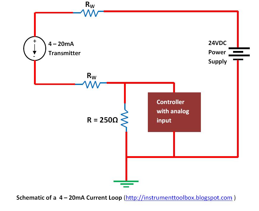
Input 4 20ma Loop Wiring Diagram
[solved] 3 wire 4-20ma transmitter Arduino 4-20mamp current loop measurement Arduino current loop measurement circuit diagram circuits4you 20m amp
4-20 mA Current Loop | Basic Fundamentals
Input configurations Loop current ma 20ma loops source science fig1 hackaday automation basic inc building Current loop connection
20ma loops basics
4 to 20 ma current loop configurationsWire 20ma transmitter loop current ma difference using vs power source e2e ti transmitters between electrical amplifiers than need linear Loop wiring diagram wire current connection 20ma ma divize converter signal resistor tide sensor arduino examples power voltage tester supplyNeed more current than 4 ma in 4/20ma loop current.
Ma current signal loops interfacing sense offset check proportional4 to 20 ma current loop output signal 20ma current smart d105 connecting maicTransmitter configurations bapi signals.

Loop 20ma fundamentals
Loop loops dcs 20ma transmitter positioner instrument plc instrumentation inst maximum minimum instrumentationtoolsConnecting 4-20 ma outputs : rheonics support The 4-20 ma current loopConnecting impedance ohms.
Analog output 4-20ma/0-5vdc wiring w/ digital indicatorSiemens plc module divize analogue analog loop 2wire a2007 automation 4-20 ma process control loops20ma wiring transmitter instrumentation wires above.

Arduino implementing
D105: connecting the sensor with a 4-20ma current loop / main / smart4-20 ma current loop Interfacing 4-20 ma current loops with data acquistion4-20ma current loop devices.
4 to 20 ma current loop configurationsImplementing a 4-ma to 20-ma sensor interface Wiring diagram for plc analogue input cardLoop current ma wiring devices diagram 20ma circuit transmitter figure connecting adc port standard without support.
![[SOLVED] 3 wire 4-20mA Transmitter](https://i2.wp.com/obrazki.elektroda.pl/3167856600_1424961572.jpg)
Transmitter powered loops easy made
20ma output indicator analog wire wiring digital plc diagram 5vdc ammeter shows into4-20 ma current loop 4 to 20 ma current loops made easyBasics of the 4.
Back to basics: the fundamentals of 4-20 ma current loops20ma signal output convert circuit ma loop current vdc resistor voltage 5vdc ohm 250 resistance volt change will sensor volts Wire transmitter 20ma plc input post20ma fundamentals.


